Lego ``Steam'' Cars

Historic steam locomotives, such as Stevenson's ``The Rocket,'' served as
inspiration for the pneumatic cars shown on this page. This picture is from
D.H. Thurston,
A History of the Growth of the Steam-Engine
(Appleton, New York, 1878).
Mark I
The compact two-cylinder engines in the cars on this page
are inspired by designs by
Dr. C. S. Soh
and
Joe Nagata, and much more
detail can be found at their web sites. The two cylinders drive the same
crankshaft,
but are 90 degrees out of phase. That way, one cylinder produces its maximum
torque when the other goes through the dead centers at the ends of its stroke.
This does away with the need for the large flywheel which helps
a one-cylinder engine
past its dead centers.
The valves, which distribute the compressed air to each side of the pistons,
are driven by a camshaft connected to the crankshaft by gears. In
Mark I, shown above, the valve and their mechanism sit inside the car,
between the cylinders and driving wheels. (Adjusting
the timing of the valves is definitely the trickiest part of building
a car that runs.) The compressed
air is produced by a pump, driven by an electric motor, and stored in the
blue tank.
The CRX brick is really only used as a glorified battery case, and these cars
could equally well be built with a standard battery case instead.
Mark II
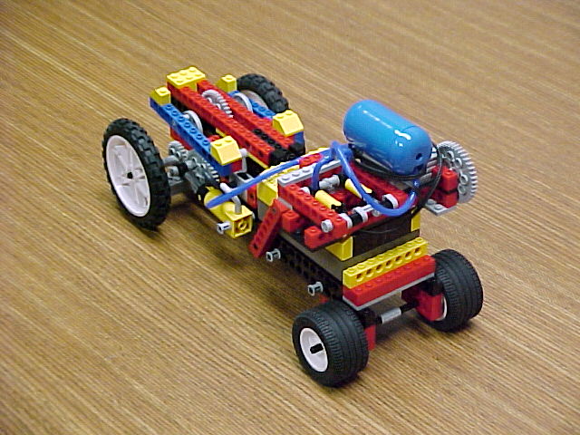

My second-generation car is Mark II. It is similar to Mark I,
but it was built to have as much as possible of the engine and the tubing
on the outside for easy viewing.
The two pictures above show full views of Mark II.
The two-cylinder pump on the front is driven by an electric motor
underneath the blue air tank. Blue tubing leads from the pump to the tank,
and from the tank to the valves.
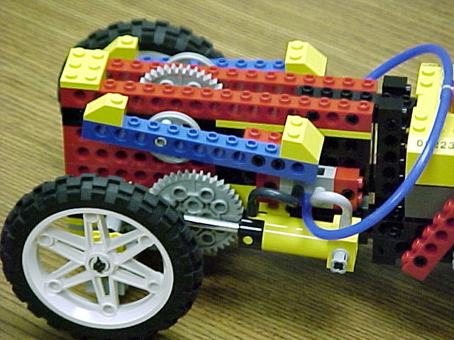

These two pictures show close-ups of of the Mark II engine; intact on
the left and with the valve rod detached from the valve on the right.
Copressed air enters the valve through the blue tube. It is directed to the
two sides of the piston through the light and dark gray tubes, according to
the position of the valve. The piston drives the large gear, which meshes
with a smaller gear on the wheel axle (hidden behind the tire). The large gears
on the right and left sides, which are 90 degrees out of phase,
are connected through the crankshaft. On the crankshaft, inside the car,
is a third large gear, which drives the camshaft through the large gear that
is seen peeking out through the top of the car. The pulleys on the
camshaft drive the valves via the valve rods. For smoothest operation,
the body of the valve is attached to the side of the car 2 1/3 Lego units
below the crankshaft. (This is a trick I learned from C.S. Soh's stationary
engine.) The cylinder pivot is at the same level as the crankshaft.
Dr. Rikvold's home page